
Truma CP plus VarioHeat
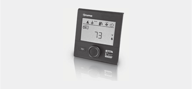
Table of contents
Consumer Safety Information
Safety Definitions ..................................................................... 3
Safety Behavior and Practices .................................................. 3
Intended use .......................................................................... 3
Important notes ..................................................................... 3
Operating Instructions
Display and Operating Elements ........................................ 4
Description ............................................................................... 4
Rotary push button ................................................................... 4
Back button .............................................................................. 4
Initial start-up ........................................................................... 4
Start-up ..................................................................................... 5
Functions .................................................................................. 5
Select setting level .................................................................... 5
Switch on / off .......................................................................... 5
Change the room temperature ................................................. 5
Select the fan level ................................................................... 6
Change hot water mode .......................................................... 7
Set the time switch ................................................................... 7
Set clock ................................................................................... 9
Service menu ............................................................................ 9
Special displays ...................................................................... 11
Warning / Error ....................................................................... 11
Warning .................................................................................. 11
IR remote control ................................................................ 12
Maintenance ........................................................................ 12
Troubleshooting charts ...................................... 14
VarioHeat (H) .......................................................................... 14
AquaGo (W) ............................................................................ 14
Aventa eco / comfort .............................................................. 16
California Proposition 65 lists chemical substances known to the state to cause cancer, birth defects, death, serious illness or other reproductive harm. This product may contain such substances.

Trademark information
Truma CP plus VarioHeat control panel referred to as CP plus VarioHeat below. Truma AquaGo referred to as AquaGo below. Truma VarioHeat comfort referred to as VarioHeat below. Aventa eco and Aventa comfort referred to as Aventa below.
VarioHeat is a furnace. For technical reasons they it referred to as “HEATING” in the display text.
|
FIRE OR EXPLOSION HAZARD Failure to follow safety warnings exactly could result in serious injury, death or property damage. |
Do not store or use gasoline or other flammable vapors and liquids in the vicinity of this or any other appliance.
WHAT TO DO IF YOU SMELL GAS
- Evacuate all persons from the vehicle.
- Shut off the gas supply at the gas container or source.
- Do not touch any electrical switch or use any phone or radio in the vehicle.
- Do not start the vehicle’s engine or electric generator.
- Contact the nearest gas supplier or certified service technician for repairs.
- If you cannot reach a gas supplier or certified service technician, contact the nearest fire department.
- Do not turn on the gas supply until gas leaks have been repaired.
Installation and service must be performed by a certified service technician, service agency, or the gas supplier.
Consumer Safety Information
Safety Definitions
![]() This is the safety alert symbol. This symbol alerts you to potential hazards that can kill or hurt you and others.
This is the safety alert symbol. This symbol alerts you to potential hazards that can kill or hurt you and others.
![]() indicates a hazardous situation which, if not avoided, could result in death or serious injury.
indicates a hazardous situation which, if not avoided, could result in death or serious injury.
![]() is used to address practices not related to physical injury.
is used to address practices not related to physical injury.
![]() Other important information or tips.
Other important information or tips.
Safety Behavior and Practices
|
|
Intended use
The CP plus VarioHeat is suitable only for installation in RVs used for recreation, travel, or camping.
The CP plus VarioHeat controls and monitors the following appliances:
- VarioHeat
- AquaGo
- Aventa eco / comfort
Important notes
- If the power supply to the system has been interrupted, the time / time switch must be reset.
- If a new or replacement appliance (furnace, air conditioning system or hot water system) is connected to the bus system, the procedure described in “Initial start-up” must be repeated.
Operating Instructions
Display and Operating Elements
 Fig. 1
- Display
- Status line
- Menu line (top)
- Menu line (bottom)
- Power supply display 120 V AC (mains supply)
- Time switch display
- Settings/Values (displayed text)
- Rotary push button
- Back button
Description
- A rotary push button (8) is used to select menu items in the menu lines (3 + 4) and to adjust settings.
- Information is shown on a backlit display (1).
- The back button (9) is used to go back to a previous menu.
Rotary push button
-
The rotary push button (8) is used to select and change setpoints and parameters; it is then tapped to save the values. Selected menu items flash.
 Turn clockwise
-
-
-
-
- The menu is scrolled through from left to right
- Increase values (+)
-
-
-
Turn counterclockwise
-
-
-
-
- The menu is scrolled through from right to left
- Reduce values (-)
-
-
-
Tap
-
-
-
-
- Save a selected value
- Select a menu item, go to the setting level
-
-
-
Press and hold
-
-
-
-
-
Main switching function – control panel on/off.
-
-
-
-
Back button
Press the back button (9) to go back to a previous menu and cancel settings. This means that the previous values remain unchanged.
Initial start-up
Perform the following steps for initial start-up:
- Switch on the power supply.
- – 12 V DC for the CP plus VarioHeat and furnace, air conditioning system or hot water system
- Start searching for the appliances in the menu item “Service menu” –> “RESET” –> “PR SET”.
Start-up
Start / Stand-by screen
When the CP plus VarioHeat is connected to the power supply, a start screen is displayed after a few seconds.
 Fig. 2
![]()
- The display alternates between the current time and the room temperature that you set.
- Special displays on command via CI-BUS (refer to “Special displays” on page 11).
- After repairs or upgrades, “initial startup” has to be repeated.
Functions
The functions of menu lines (Fig. 1 – 3, 4) of the CP plus VarioHeat can be selected in any sequence. The operating parameters are shown in the status line (Fig. 1 – 2) or in the display (Fig. 1 – 6).
Select setting level
- Tap the rotary push button.
The display shows the setting level. The first icon flashes.
 Fig. 3
Switch on / off
Switch on
- Tap the rotary push button.
![]() Previously set values and operating parameters are active again when the panel is switched on.
Previously set values and operating parameters are active again when the panel is switched on.
Switch off
- Press the rotary push button for more than 4 seconds.
![]() The switch off process of the CP plus VarioHeat may take a few minutes due to internal time lags of the furnace, air conditioning system or hot water system (“OFF” is displayed during this time).
The switch off process of the CP plus VarioHeat may take a few minutes due to internal time lags of the furnace, air conditioning system or hot water system (“OFF” is displayed during this time).
 Change the room temperature
- Use the rotary push button (Fig. 1 - 8) to select the icon in the menu line (Fig. 4 – 3).
- Tap the rotary push button to go to the setting level.
- Use the rotary push button to select the furnace (“HEATER”) or air conditioning system (“AC”).
- Tap the rotary push button to confirm the selection.
- Use the rotary push button to select between “OFF”, “VENT”, “COOL”, “AUTO”.
- Push rotary push button to confirm the selection.
- Select the desired temperature with the rotary push button.
- Tap the rotary push button to confirm the value.
 Fig. 4
Furnace (“HEATER”)
Adjustable temperature range 40 – 86 °F (1 °F increments) or 5 – 30 °C (1 °C increments)
-
a = Furnace on – icon is lit; the icon flashes until the room temperature is reached.
Air conditioning system (“AC”)
Adjustable temperature range 60 - 88 °F (1 °F increments) or 16 – 31 °C (1 °C increments)
![]() Air conditioning system can also be operated with IR remote, see page 12.
Air conditioning system can also be operated with IR remote, see page 12.
|
Icon |
Displayed text |
Description |
|
b |
COOL |
Air conditioning system is switched on |
|
c |
AUTO 1 |
Air conditioning system is set to automatic |
|
d |
NIGHT |
Air conditioning system is set to silent mode |
|
d |
VENT |
Air conditioning system is in air circulation mode |
1 Symbol flashes until the desired room temperature is reached.
![]() Quick temperature change possible using rotary push button (in stand-by screen).
Quick temperature change possible using rotary push button (in stand-by screen).
Automatic climate control (“AUTO”)
Adjustable temperature range 64 - 77 °F (1 °F increments) or 18 - 25 °C (1 °C increments)
Automatic changeover between furnace and air conditioning system for an approximately constant temperature inside the vehicle.
-
e = AUTO – Automatic climate control is activated
Requirements for operation with automatic climate control:
- The furnace and air conditioning system must be connected.
- Automatic climate control (ACC) must be activated in the service menu (see “Service menu” page 9)
With a furnace / AC connected
- Use the rotary push button to select the icon in the menu line (Fig. 5 – 3).
- Tap the rotary push button to go to the setting level.
- Select the desired fan level with the rotary push button.
- Tap the rotary push button to confirm the value.
 Fig. 5
![]() The temperature range below 41 °F (5 °C; “OFF”) must be selected in order to switch off the furnace.
The temperature range below 41 °F (5 °C; “OFF”) must be selected in order to switch off the furnace.
Furnace (“HEATER”)
|
Icon |
Displayed text |
Description |
|
– |
OFF |
Fan is switched off. (only selectable if no appliance is in operation). |
|
g |
ECO |
Low fan level |
|
h |
HIGH |
High fan level |
|
i |
BOOST |
Rapid room heating Available if the difference between the selected and actual room temperature is >10 °C (depends on connected heating appliance) |
![]() When the furnace is switched on (room temperature set), the fan level selected in the previous heating process is shown in the status line (Fig. 1 – 2). The default setting is “AUTO”.
When the furnace is switched on (room temperature set), the fan level selected in the previous heating process is shown in the status line (Fig. 1 – 2). The default setting is “AUTO”.
Air conditioning system (“AC”)
Air conditioning system can also be operated with IR remote, see page 12.
|
Icon |
Displayed text |
Description |
|
– |
OFF |
Fan is switched off (can be selected only if no appliance is in operation). |
|
g |
LOW |
Low fan level |
|
h |
MID |
Medium fan level |
|
i |
HIGH |
Highest fan level |
|
j |
NIGHT |
Ultra-quiet fan operation for both the indoor and outdoor fans (only available in cooling mode) |
 Change hot water mode
- Use the rotary push button to select the icon in the menu line (Fig. 6 – 3).
- Tap the rotary push button to go to the setting level.
 Fig. 6
![]() If the warning “CLEAN” is displayed, the AquaGo must be decalcified (see “2.2 CLEAN” page 10).
If the warning “CLEAN” is displayed, the AquaGo must be decalcified (see “2.2 CLEAN” page 10).
3. Select the desired hot water mode with the rotary push button.
4. Tap the rotary push button to confirm the selection.
5. Select the desired hot water temperature with the rotary push button 95 - 120 °F (35 - 49 °C).
6. Tap the rotary push button to confirm the value.
Hot water mode
| Icon | Displayed | Description text |
| -- | OFF | AquaGo is switched off. |
| l | ECO | The AquaGo is now running in energy-saving mode. |
| m | COMFOR | The AquaGo is now running in a mode that provides rapid availability of hot water. |
| n | ANTIFR |
Prevention of freezing using 12 V DC electricity:
|
 Set the time switch
|
The enabled time switch switches the furnace on, even when the recreational vehicle (RV) is parked. The exhaust gas from the furnace can cause poisoning in enclosed spaces (e.g. garages, repair shops). If you park the RV in an enclosed space: 1. Block the fuel supply (gas) to the furnace. 2. Disable the time switch of the CP plus VarioHeat (OFF). 3. Switch off the furnace on the CP plus VarioHeat . |
![]() If the time switch is “ON”, the “Disable time switch (“OFF”)” menu is displayed.
If the time switch is “ON”, the “Disable time switch (“OFF”)” menu is displayed.
- Use the rotary push button to select the icon in the menu line (Fig. 1 – 4).
- Tap the rotary push button to go to the setting level.
Enter start time
Use the rotary push button to set the hours and then the minutes.
24 h mode 12 h mode
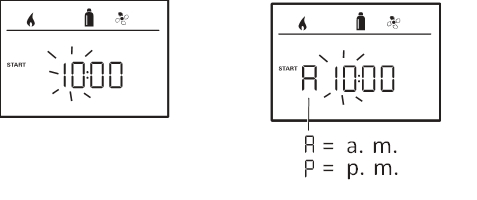
Fig. 7 Fig. 8
Enter end time
Use the rotary push button to set the hours and then the minutes.
24 h mode 12 h mode
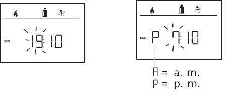
Fig. 9 Fig. 10
![]() If the start/end time is earlier than the time when you entered the settings, the operating parameters are not active until the next start/end time is reached. Until then, the operating parameters set outside the time switch remain valid.
If the start/end time is earlier than the time when you entered the settings, the operating parameters are not active until the next start/end time is reached. Until then, the operating parameters set outside the time switch remain valid.
Set room temperature
- Depending on the connected appliance, use the rotary push button to choose between furnace or AquaGo.
- Tap the rotary push button to confirm the selection.
- Select the desired room temperature with the rotary push button.
- Tap the rotary push button to confirm the value.
 Fig. 11
Select fan level
- Select the desired fan level with the rotary push button.
- Tap the rotary push button to confirm the value.
 Fig. 12
Select the hot water temperature
- Select the desired hot water mode with the rotary push button.
- Tap the rotary push button to confirm the selection.
- Select the desired hot water temperature with the rotary push button 95 - 120 °F (1 °F increments) or 35-49 °C (1 °C increments).
- Tap the rotary push button to confirm the value.
Enable time switch (“ON”)
- Enable the time switch (ON) with the rotary push button
- Tap the rotary push button to confirm the value.
 Fig. 13
![]() The time switch remains enabled, even for several days, until it is disabled (“OFF”). If the time switch is programmed and enabled, the time switch icon flashes.
The time switch remains enabled, even for several days, until it is disabled (“OFF”). If the time switch is programmed and enabled, the time switch icon flashes.
Disable time switch (“OFF”)
- Tap the rotary push button to go to the setting level.
- Disable the time switch (“OFF”) with the rotary push button
- Tap the rotary push button to confirm the value.
 Fig. 14
 Set clock
Display 24 h mode Display 12 h mode
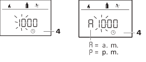
Fig. 15 Fig. 16
Use the rotary push button (Fig. 1 – 8) to select the “Set clock” icon in the menu line (Fig. 1 - 4). The hour display flashes.
- Use the rotary push button (Fig. 1 – 8) to set the hours.
- Tap the rotary push button again and the minute display flashes.
- Use the rotary push button to set the minutes.
- Tap the rotary push button to confirm the value.
Service menu
1. Calibrate room temperature sensor of the furnace (“OFFSET”)
The room temperature sensor of the connected furnace can be adjusted individually to suit the location of the sensor. Settings can be made in the range from 41 °F to 23 °F (5 °C to -5 °C) in 1 °F (0.5 °C) increments.
 Example:
Set room temperature 75 °F; OFFSET = -1 °F;
Setpoint for furnace = 74 °F
Fig. 17
Default setting: 0 °F (0 °C).
2. AC SET
(Only available if ACC is set to “ON”)
The sensed room temperature can – during operation of the automatic climate control – be perceived differently during cooling than during heating. “AC SET” is used to set an offset between cooling and heating. The setting can be made in increments of 1 °F (0.5 °C) within the range of 0 °F to 10 °F (0 °C to 5 °C).
 Example:
Set room temperature 74 °F; AC SET = 2 °F
– Setpoint value for air conditioning system = 76 °F
Fig. 24
Presetting: +2 °F (+1 °C).
3. ACC
(Only available if the air conditioning system and furnace are connected)
The automatic climate control function AUTO is activated or blocked with “ACC”.
ON
– The automatic climate control function AUTO is activated. Automatic climate control function AUTO can be selected in the Room temperature menu.
– “AC SET” appears in the Service menu.
OFF
– The automatic climate control function AUTO is blocked.
 Fig. 25
Presetting: OFF
![]() The function of the Truma automatic climate control depends on proper installation.
The function of the Truma automatic climate control depends on proper installation.
4. AquaGo
![]() Available only when AquaGo is connected.
Available only when AquaGo is connected.
4.1 CALCI
Indicates the relative level of calcification of the AquaGo as a percentage.
![]() With 100 % calcification, the warning “CLEAN” is displayed in the Hot water mode menu (see “Change hot water mode” page 7) and the AquaGo must be decalcified.
With 100 % calcification, the warning “CLEAN” is displayed in the Hot water mode menu (see “Change hot water mode” page 7) and the AquaGo must be decalcified.
4.2 CLEAN
(Only AquaGo comfort / AquaGo comfort plus.)
![]() Irritation of skin and eyes in case of contact with decalcification agent Wear protective gloves, eye protection and face protection to avoid contact.
Irritation of skin and eyes in case of contact with decalcification agent Wear protective gloves, eye protection and face protection to avoid contact.
![]() The directions in the AquaGo operating instructions must be followed.
The directions in the AquaGo operating instructions must be followed.
Starts or stops the decalcification process.
![]() The AquaGo operating instructions contain a complete description of the decalcification process (see “Decalcification”).
The AquaGo operating instructions contain a complete description of the decalcification process (see “Decalcification”).
Start = starting decalcification
Stop = interrupting decalcification
![]() When the decalcification process is interrupted, the AquaGo is automatically rinsed and can be used only after this.
When the decalcification process is interrupted, the AquaGo is automatically rinsed and can be used only after this.
4.3 HARDN
![]() The appliance must be decalcified regularly depending on water hardness and hot water consumption.
The appliance must be decalcified regularly depending on water hardness and hot water consumption.
Specify the hardness of the water that is used. Is needed to display the relative calcification of the AquaGo (see “2.1 CALCI”).
Default = 1
|
Level |
Water hardness (mg/l CaCO3) |
|
1 |
Soft 0 - 60 |
|
2 |
Moderately hard 61 - 120 |
|
3 |
Hard 121 - 180 |
|
4 |
Very hard > 180 |
5. °C / °F temperature display
Select temperature display °C (Celsius) or °F (Fahrenheit).
 Fig. 18
Default setting: °C (Celsius).
6. Change backlighting
Change the backlighting of the CP plus VarioHeat in 10 increments.
 Fig. 19
7. 12 h / 24 h Mode
Display in 12 h (a. m., p. m.) / 24 h mode.
 Fig. 20
Default setting: 24 h mode
8. Change language
Select the desired language (German, English, French, Italian).
 Fig. 21
Default setting: English
9. Show the version number
Display the version number of the furnace, AquaGo and CP plus VarioHeat .
 Example:
H 1.20.01 –> H = appliance; 1.20.01 = Version number
Appliance
P = CP plus VarioHeat, CP plus VarioHeat, CI-BUS
H = VarioHeat
W = AquaGo
Fig. 22
10. RESET
The reset function resets the CP plus VarioHeat to the factory settings. All your settings are deleted. Newly connected devices are recognized and recorded in the control panel.
-
Switch on the power supply – 12 V DC for the CP plus VarioHeat and VarioHeat furnace
Reset
- Select “RESET” with the rotary push button (Fig. 1 – 8).
- Tap the rotary push button.
- “PR SET” is shown in the display.
- Tap the rotary push button to confirm.
 Fig. 23
When you have confirmed the selection, the CP plus VarioHeat is initialized.
“INIT ..” appears on the display while this is in progress.
Special displays
External control panel (CI-BUS)
![]() If a command is sent from an external control panel with CI-BUS, “CI” is displayed.
If a command is sent from an external control panel with CI-BUS, “CI” is displayed.
The CP plus VarioHeat CI-BUS is a separate variant that is fitted only in the factory.
Display energy type
In heating mode, gas (a) is shown as the energy type
 Fig. 24
 Warning / Error
Warning
If an operating parameter is outside the target range, the CP plus VarioHeat immediately jumps to the “Warning / Error” menu level and displays the respective fault code. The cause of the warning can be determined and remedied with the aid of the troubleshooting guide (from page 14 and ff).
Return to setting level
- Tap the rotary push button or press the back button. If the display is in stand-by mode, tap to activate the background lighting and tap again to acknowledge the warning.
![]() If possible, the appliance concerned continues to operate. When the operating parameter is within the target range again, this icon extinguishes again automatically.
If possible, the appliance concerned continues to operate. When the operating parameter is within the target range again, this icon extinguishes again automatically.
Display warning code
- Select the icon (“Fig. 25”) with the rotary push button.
- Tap the rotary push button.
- The code of the current warning is displayed. The troubleshooting chart (refer to “Troubleshooting” on page 14 and ff) can be used to determine the cause of the warning and remedy the error.
 Fig. 25
 W = Warning
28 = Error code
H = Appliance
H = VarioHeat
W = AquaGo
Fig. 26
Malfunction
In the event of an error, the CP plus VarioHeat immediately jumps to the “Warning / Error” menu level and displays the respective fault code. The cause of the error can be determined and remedied with the aid of the troubleshooting guide (from page 37 and ff).
E = Error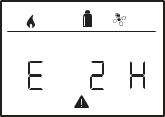
2 = Error code
H = Appliance
H = VarioHeat
W = AquaGo
Fig. 27
Cause remedied / return to setting level
-
Tap the rotary push button.
-
The respective appliance is restarted.
-
![]() This may take a few minutes due to internal time lags of connected appliances. If the cause was not remedied, the malfunction will occur again and the control panel will again go to the “Warning / Error” menu level.
This may take a few minutes due to internal time lags of connected appliances. If the cause was not remedied, the malfunction will occur again and the control panel will again go to the “Warning / Error” menu level.
Cause not remedied / return to setting level
-
Press the back button.
Reading out the error fault code
When the error has been acknowledged, the fault code can be opened again:
- Select the warning symbol (Fig. 25) with the rotary push button.
- Tap the rotary push button. The current error fault code is displayed.
IR remote control
Air conditioning systems – shared use of IR remote control and CP plus VarioHeat
- Even after connecting the CP plus VarioHeat, the IR remote control is still available to control the air conditioning system. The CP plus VarioHeat recognises all settings (except dehumidification mode) that are made on the air conditioning system using the IR remote control. The IR remote control only transmits the settings that are shown in its display (no bidirectional communication).
- Only the time switch of the CP plus VarioHeat may be used to clearly define the start and end time of a required period.
Maintenance
The CP plus VarioHeat is maintenance-free.
To clean the front, you can use a non-abrasive cloth moistened with water (and a neutral soap solution).
Technical data
Display
LCD, monochrome, with backlighting
Diagonal 3.3 in. (84 mm)
Dimensions (L x W x H)
3.62 x 4.06 x 1.58 in. (92 x 103 x 40 mm)
Operating temperature range
13 °F to 140 °F (-25 °C to +60 °C)
Storage temperature range
13 °F to 158 °F (-25 °C to +70 °C)
Interface
TIN bus
CI-BUS (only CI-BUS model)
Power supply
8 – 16.5 V DC
Power consumption
max. 65 mA (100% backlighting)
10 mA (stand-by)
|
Quiescent current 3 mA (Off) |
|
|
Weight approx. 0.22 lb |
(approx. 100 g) |
|
Protection class Class III |
|
Protection type IP00
Subject to change without notice.
Troubleshooting charts
VarioHeat (H)
|
Error code |
Potential cause |
Solution |
|
E 2 H, E 16 H |
Flame not detected: Gas cylinder empty |
Replace gas cylinder |
|
Gas cylinder or quick-acting valve in the gas supply line closed |
Check the gas infeed and open the valves |
|
|
Butane concentration in the gas cylinder too high |
Use propane. Butane is not suitable for heating, especially at temperatures below 50° F (10 °C) |
|
|
|
Combustion air infeed or exhaust gas outlet closed |
Check openings for dirt (slush, ice or leaves) and remove |
|
W 25 H |
Excess voltage > 16.4 V DC |
Check battery voltage and power sources, such as battery charger |
|
W 26 H |
Undervoltage, battery voltage too low < 10 V DC |
Charge the battery, replace old battery |
|
W 27 H |
Warm air outlets blocked Circulated air intake blocked EN end outlet closed |
Remove blockage Remove blockage Open EN end outlet |
|
W 29 H |
Imminent undervoltage, battery voltage too low < 10.4 V C |
Charge battery |
|
W 255 H |
Furnace has no 12 V DC power supply |
Ensure 12 V DC power supply |
|
No connection between furnace and control panel |
Connect furnace and control panel |
If these measures do not remedy the malfunction or if error codes are displayed that you cannot find in the troubleshooting chart, contact your dealership, Truma Service 1-855-558-7862 or one of our authorized Service Partners.
AquaGo (W)
|
Error code |
Potential cause |
Solution |
|
E 1 W |
Flame not detected |
There is a flame-detection error at the burner because the flame was not detected after release of gas and ignition. Important: The system indicates this error only after three attempts at intervals of approximately 30 seconds. |
|
E 2 W |
Error at over temperature switches (EOS, BOS) |
The exhaust over temperature switch (EOS) or burner over temperature switch (BOS) is open/ unplugged. |
|
E 3 W |
Error at exhaust pressure switch (EPS) |
The EPS did not close when the flue fan was actuated because the fan did not push enough air through the exhaust channel. A cause could be, e.g., blocking of the exhaust channel or a faulty switch. OR The EPS is closed even though the flue fan is not running. Cause is a defective EPS or flue fan. |
|
E 4 W |
Error at water over temperature switch (WOS) |
The WOS opened at a water temperature of over 185 °F (85 °C). |
|
Error code |
Potential cause |
Solution |
|
E 5 W |
Flame detected at incorrect time |
There is an error in flame detection of the burner because the flame was detected: before ignition or before the release of gas or after the gas was switched off. |
|
E 6 W |
Error in the safety circuit for gas valve |
There is a heating request but gas cannot be released. One of the switches WOS, EOS, BOS, EPS is open/unplugged. |
|
E 7 W |
Error of burner MCU internal RAM |
Error detected in the burner MCU’s internal safety monitoring feature (safety variables are no longer correct or RAM/STACK was overwritten by mistake). |
|
E 9 W |
Malfunction of water outlet temperature sensor WOT |
Water outlet temperature sensor WOT has a short circuit or is open/unplugged. the temperature of the sensor is colder than 14 °F (-10 °C). |
|
E 10 W |
Error in the safety circuit |
There is a heating request but gas is not released because a valve-actuation signal was not activated. |
|
E 11 W |
Error of MCU watchdog gas release |
There is a heating request but the MCU watchdog does not release the gas path. |
|
W 12 W |
Internal error |
|
|
W 13 W |
Short circuit shut-off valve |
Short circuit detection in the gas valve (shutoff part) detected a current > 1000 mA and shut off. |
|
W 16 W |
Malfunction of the MCU |
Internal error of the control unit. |
|
W 20 W |
Malfunction of water inlet temperature sensor WIT |
Water inlet temperature sensor WIT has a short circuit or is open/unplugged or the temperature of the sensor is colder than 14 °F (-10 °C). |
|
W 21 W |
Malfunction of circulation line temperature sensor WCT |
Circulation line temperature sensor WCT has a short circuit or is open/unplugged or the temperature of the sensor is colder than 14 °F (-10 °C). |
|
E 22 W |
Malfunction of gas valve, modulation section |
Error at gas valve, modulation level, because the modulator has a short circuit or is open/unplugged. |
|
W 23 W |
Voltage is too high |
The main power supply’s voltage detector measured a voltage level of >16.4 V. |
|
W 24 W |
Voltage is too low |
The main power supply’s voltage detector measured a voltage level of <10 V. |
|
E 25 W |
Flue fan current consumption error |
The current detector for the flue fan has measured a current outside the permitted limits. |
|
W 26 W |
Circulation pump current consumption error |
The current detector at the circulation pump has measured a current outside the permitted limits. |
|
Error code |
Potential cause |
Solution |
|
W 27 W |
Water circulation pump is running dry. |
The circulation pump does not generate water flow. The water system may not be filled or not sufficiently vented. The circulation pump tries (20 times) to generate a water flow every 30 s (if successful, the error is reset). |
|
W 28 W |
Too low gas pressure. |
Gas supply (in vehicle) to the appliance insufficient. |
|
W 29 W |
Too high heat power required. |
You are trying to use more hot water than the appliance can supply. |
|
W 30 W |
Risk of freezing. |
Temperature in the appliance below 27 °F (3 °C). |
|
W 31 W |
Decalcification finished. |
– |
|
W 32 W |
Current too low. |
Current in the antifreeze kit too low (e.g. cable break). |
|
W 33 W |
Current too high. |
Current in the antifreeze kit too high (e.g. short circuit). |
If these measures do not remedy the malfunction or if error codes are displayed that you cannot find in the troubleshooting chart, contact your dealership, Truma Service 1-855-558-7862 or one of our authorized Service Partners.
Aventa eco / comfort
|
Error code |
Cause |
Remedy |
|
34, 47 |
Unstable 120 V power supply in connection with generator or inverter operation |
Ensure shore power supply 120 V at the unit input |
If none of the measures in the troubleshooting chart proves successful or fault codes are displayed that cannot be found in the troubleshooting chart, please contact the Truma Service Center at 1-855-558-7862 or one of our authorized service partners.
In case you encounter any problems, please contact the Truma Service Center at 855-558-7862 or one of our authorized service partners. For details see www.truma.net.
Please have the model number and serial number (on type plate of appliance) handy when you call.
Manufacturing Sales
Truma Gerätetechnik Truma Corp
GmbH & Co. KG 2800 Harman Drive
Wernher-von-Braun-Straße 12 Elkhart, IN 46514
85640 Putzbrunn USA
Germany Toll Free 1-855-558-7862 www.truma.com Fax 1-574-538-2426
service@trumacorp.com www.truma.net