
Project M – AGM/Lithium Power Solution Install Information
AGM/Lithium Power Solution

|
AGM Power Solution Accessories |
||
|
Part |
FWC PN |
QTY. |
|
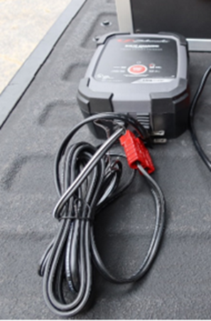
Schumacher 8A Converter W/ SB50 Connector |
ECH-0004 |
1 |
|
Potek 750W Inverter W/ SB50 Connector |
EVC-0005 |
1 |
|
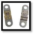
Spare 80A MIDI Fuses |
EFU-0006 |
2 |
|
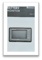
Renogy Battery Monitor Manual |
--- |
1 |
|
Lithium Power Solution Accessories |
||
|
Part |
FWC PN |
QTY. |
|
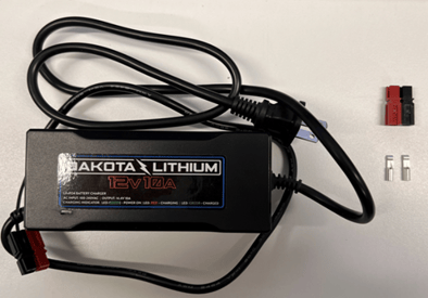
Dakota Lithium 10A Converter W/ PowerPole connectors |
ECH-0007 |
1 |
|
Potek 750W Inverter W/ SB50 Connector |
EVC-0005 |
1 |
|
Spare 80A MIDI Fuses |
EFU-0006 |
2 |
|
Renogy Battery Monitor Manual |
--- |
1 |
|
AGM/Lithium Power Solution Standard Installation Parts |
|||
|
Item No. |
Part |
FWC PN |
QTY. |
|
1 |
Fuse Panel, ATC, 8 Gang |
EFP-0002 |
1 |
|
2 |
Panel Mounting Plate |
N/A |
1 |
|
3 |
Screw, Phillips Pan, (Stainless Steel)#8-15 x 1-1/2" |
FSC-0033 |
4 |
|
4 |
Screw, Phillips Pan, (Black)#8-15 x 1" |
FSC-0032 |
2 |
|
5 |
11 1/2" L-Track |
ABT-0002 |
2 |
|
6 |
L-Track End Cap |
ACA-0005 |
2 |
|
7 |
L-Track Stud with Ring |
HPU-0035 |
4 |
|
8 |
Binding Post, Phillips Pan, (Zinc)5/16"-18 x 1" |
FBP-0001 |
4 |
|
9 |
5/16"-18 x 1-1/4" Phillips Pan Head Screw |
FSC-0059 |
4 |
|
10 |
Washer, Flat, (Zinc)1/4" |
FWA-0009 |
4 |
|
11 |
1" x 7' Black Endless Cambuckle Strap |
HST-0037 |
2 |
|
12 |
Connector, Quick Disconnect, (Blue)14-16 ga, Female |
ECO-0011 |
5 |
|
13 |
Connector, Ring Terminal, (Blue)14-16 ga, #10 Stud |
ECO-0016 |
1 |
|
14 |
Connector, Powerpole Connector, (Red/Black)30 Amp |
ECO-0030 |
1 set |
|
15 |
Fuse, ATC (Blade), (Brown)7-1/2 A (For Roof Power) |
EFU-0001 |
1 |
|
16 |
Fuse, ATC (Blade), (Light Blue)15 A (For Flood Lights) |
EFU-0003 |
1 |
|
17*** |
Wire Track |
ABT-0005 |
*32 5/8 in |
|
20*** |
Screw, Quad Flat, (Zinc)#8-15 x 1-1/4" |
FSC-0037 |
6 |
|
32 |
**Wire, Stranded, (Red)14 ga |
EWI-0012 |
66 in |
|
33 |
**Wire, Stranded, (Black)14 ga |
EWI-0006 |
66 in |

|
AGM/Lithium Power Solution Truck Charging Parts |
|||
|
Item No. |
Part |
FWC PN |
QTY. |
|
3 |
Screw, Phillips Pan, (Stainless Steel)#8-15 x 1-1/2" |
FSC-0033 |
4 |
|
18 |
Redarc BCDC Charger |
ECH-0006/5 |
1 |
|
21 |
Washer, Back-Up, (Aluminum)3/16" |
FWA-0002 |
1 |
|
22 |
Wire, Stranded, (Red)8 ga (not pictured) |
EWI-0022 |
12ft |
|
23 |
Wire, Stranded, (Black)8 ga (not pictured) |
EWI-0021 |
12ft |
|
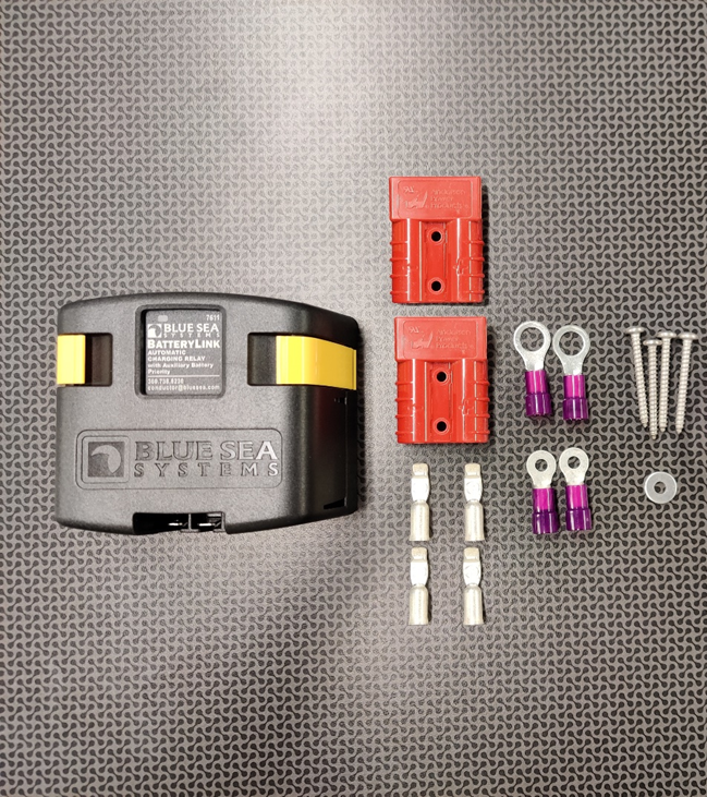
24 |
SB50 Connector with clips |
ECO-0034 |
2 |
|
25 |
Connector, Ring Terminal, (Purple)8 ga, 3/8" Stud |
ECO-0018 |
2 |
|
26 |
Connector, Ring Terminal, (Purple)8 ga, #10 Stud |
ECO-0017 |
2 |
|
AGM/Lithium Power Solution Truck Charging Install Parts |
|||
|
Item No. |
Part |
FWC PN |
QTY. |
|
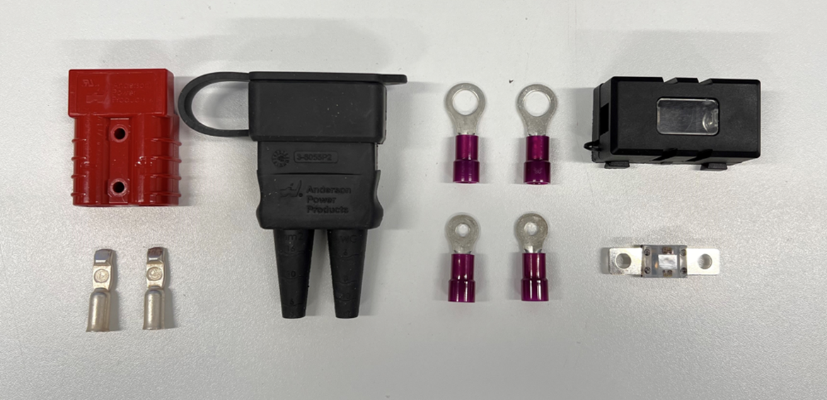
24 |
SB50 Connector with clips |
ECO-0034 |
1 |
|
25 |
Connector, Ring Terminal, (Purple)8 ga, 3/8" Stud |
ECO-0018 |
2 |
|
26 |
Connector, Ring Terminal, (Purple)8 ga, #10 Stud |
ECO-0017 |
2 |
|
27 |
SB50 Environmental Boot with Cover, Source Side |
ECO-0035 |
1 |
|
30 |
Wire, Jacketed, (Black-White) 8/2 ga (not pictured) |
EWI-0055 |
17 ft |
|
34 |
Fuse, MIDI, 40 Amp |
|
1 |
|
35 |
Fuse Holder, MIDI |
|
1 |
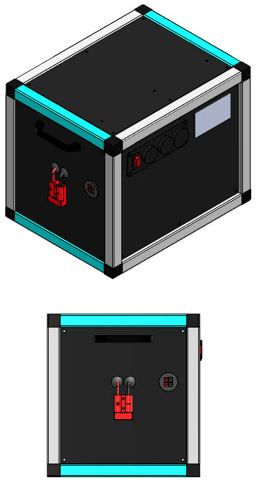
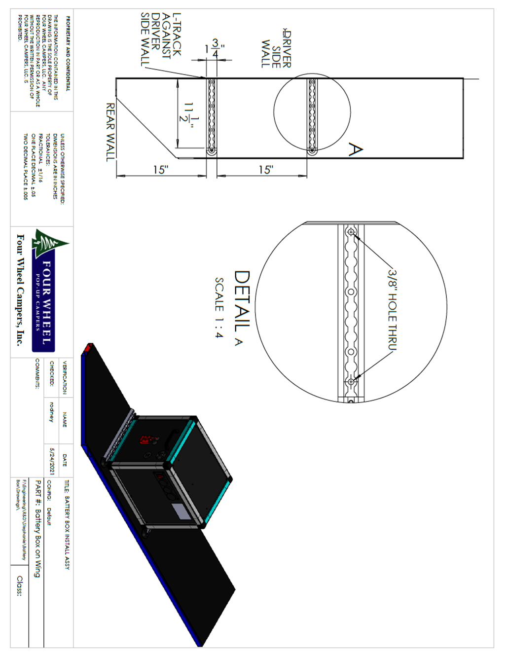
AGM/Lithium Power Solution Mounting Instructions
(see diagram below)
- Prepare the mounting of the AGM Power Solution by measuring 15” from the rear wall. Mark this distance on the driver side wing of the Project M topper.
- Place the first piece of L-track at the 15” marker that was just made and push it flush against the driver side wall.
- Clamp the L-track to the wing and drill 3/8” diameter holes in each of the furthest full circles of the L-track. Make sure to drill through both the L-track and the wing of the Project M.
- Insert the binding posts into each hole, from the bottom of the wing. Then, use 5/16”-18x1” screws from the top of the L-track to tighten the binding posts up, and fasten the L-track to the wing.
- Now that the first L-track is in place, mark 15” from the right edge of the L-track towards the front of the Project M. This will mark the left edge of the second L-track.
- Repeat steps 2-5 with the second piece L-track.
- Insert the endcaps into each L-track to help prevent injury.
- Insert 2 L-track studs with rings into each of the L-tracks. Place the studs as far away from each other as possible to create optimal tie-down locations for the straps.
- Place the AGM Power Solution between the two L-tracks, back against the driver side wall.
- Use the two 7’ cam buckle straps to fasten the AGM Power Solution to the wing. Start with the buckle on the top of the AGM Power Solution. The order to run the straps goes as follows:
- Through left box handle
- Through front stud ring on left L-track
- Back up through left box handle
- Through right box handle
- Through front stud ring on right L-track
- Back up through right box handle
- Finish through cam buckle strap
- Tighten the cam buckle strap and ensure that it only loosens when release button pressed.
- If the cam buckle loosens easily, the strap may have been pulled through the cam buckle the wrong way. Run the strap through the buckle the opposite way and test for security.
- Repeat the process with the second cam buckle strap, instead running it through the rear stud rings.
- Check to make sure the box is tightly secured to the wing.
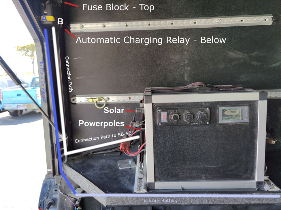
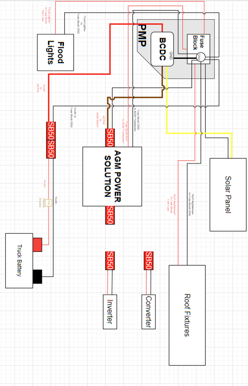
AGM/Lithium Power Solution with Truck Wiring Instructions
(see diagrams below)
- If the Project M is equipped with the older, rounded wire cover, begin with removing the wire cover from the driver side rear corner.
- Label the wires located at the driver side rear corner to ease the process of installation.
- Purple and black – Brake light wires
- Yellow and black – Roof fixture wires
- Red and black – Solar wires
- Green and black – Flood light wires
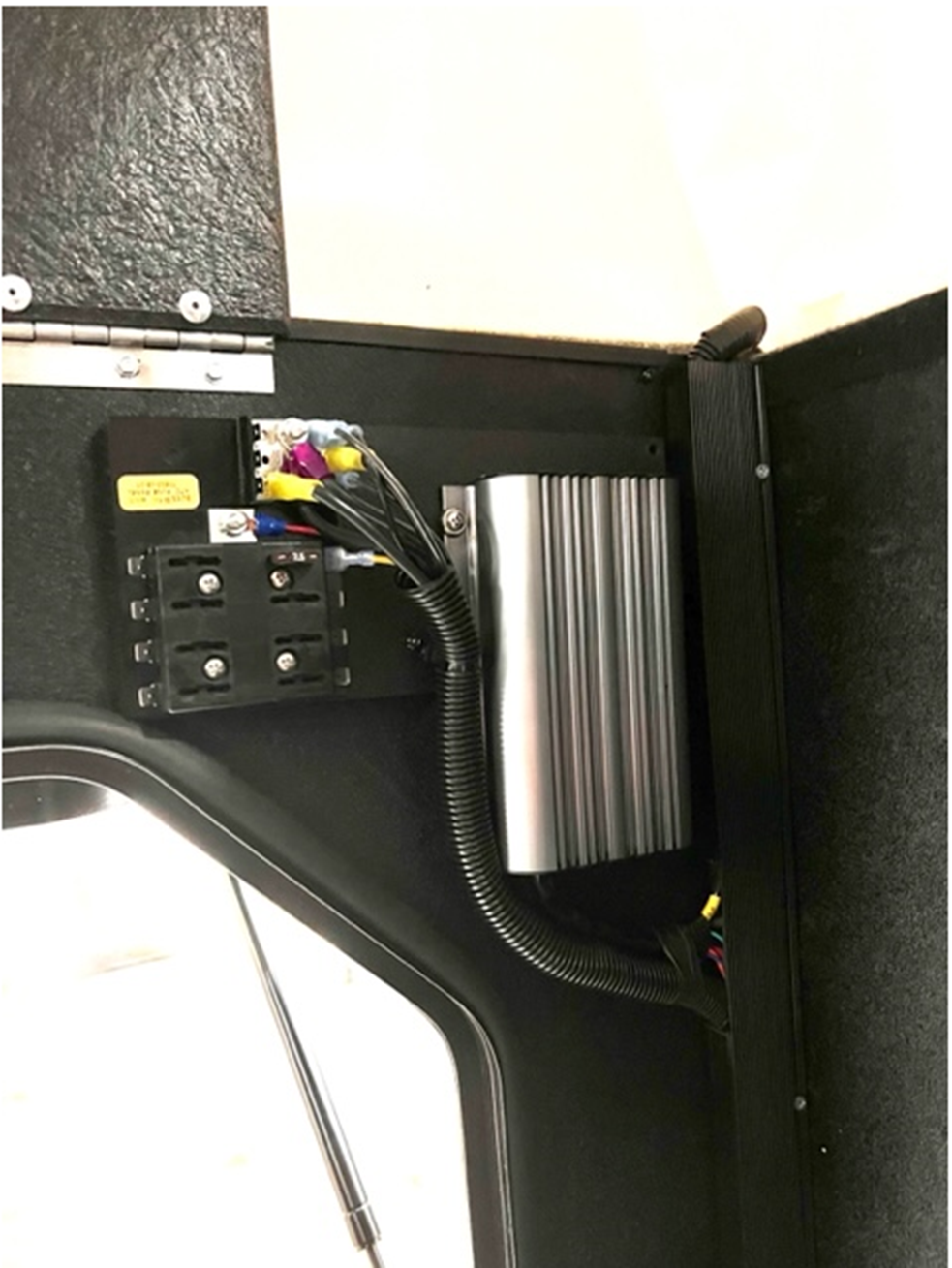
- Place the Fuse block on the Panel Mounting Plate, lining up the 4 holes on the fuse block. Use #8-15 x 1-1/2” screws to attach the fuse block to the PMP, and the PMP to the rear wall of the Project M.
- Also use #8-15 x 1-1/2” screws to screw the BCDC charger through the PMP and into the rear wall of the Project M.
- Separate the brake wire and solar wire from the roof fixtures and flood light wires.
- Take the roof fixture wires (yellow and black) and cut to length to connect them to the fuse block.
- Use 14GA female quick disconnects to connect the positive and negative into the fuse block.
- Connect yellow wire into 7.5A fuse spot.
- If equipped with flood lights, take the flood light wires (green and black) and run them from the switch, up the wall, to the fuse panel.
- Use 14GA female quick disconnects to connect the positive and negative into the fuse block.
- Connect green wire into 15A fuse spot.
- If equipped with solar:
- Cut the positive wire to length, and connect with the yellow wire of the bcdc charger using a butt connector
- Cut the negative wire to length, and ground at the fuse block using a quick disconnect
- Using 14GA wire, run from the fuse block negative and positive, down the wall to the AGM Power Solution PanelPole plug.
- Use a 14GA female quick disconnect to connect the negative wire into the fuse block.
- Use a 14GA #10 stud ring connector to connect the positive wire into the fuse block.
- Crimp a Powerpole contact onto each wire and attach the appropriately colored Powerpole housing onto each wire.
- Plug the set of Powerpoles into either pair of connectors in the AGM Power Solution PanelPole.
- Connecting the BCDC charger to the fuse panel.
- Using 8GA black wire, connect the black wire from the BCDC charger to ground at the fuse block, using a ring terminal
- Connecting the BCDC charger to the Power Solution
- Take 6ft of 8GA black wire; crimp an 8GA #10 ring terminal to one end, and an SB50 powerpole contact to the other end.
- Attach the ring terminal of the black wire to the ground on the fuse block.
- Run the black wire down the wall and clip the contact into the negative side of an SB50 connector.
- Take 5ft of 8GA red wire; crimp an SB50 contact on one end
- Crimp the other end to the brown wire of the BCDC charger using a butt connector
- Run the red wire down the wall and clip the contact into the positive side in the same SB50 connector.
- Now that both wires are clipped into an SB50 connector, plug them into SB50 connector on the left wall of the AGM Power Solution.
- Connecting the BCDC charger to the truck breakoff SB50 connector
- Take 6ft of 8GA black wire; crimp an 8GA #10 ring terminal to one end, and an SB50 powerpole contact to the other end.
- Attach the ring terminal of the black wire to the ground on the fuse block.
- Run the black wire down the wall and clip the contact into the negative side in an SB50 connector.
- Take 5ft of 8GA red wire; crimp an SB50 contact on one end
- Crimp the other end to the red wire of the BCDC charger using a butt connector
- Run the red wire down the wall and clip the contact into the positive side in the same SB50 connector.
- Now that both wires are clipped into an SB50 connector, the SB50 connector can rest on the rear corner of the wing. This will connect to the truck-side wiring.
- Cut a notch in wire track just below the BCDC charger (3” long) to allow the wires from the fuse block and BCDC to enter, and a notch in the bottom of the wire track (1” long) to allow truck power and wires to box to exit.
- Since the screw side of the track should be placed against the driver wall, the notches should be cut in the side facing the passenger wall.
- Use preferred saw to cut a rectangular notch in the side of the track.
- Bundle wires tightly against rear driver corner to fit under wire track.
- Retape the wire harness and use zip-ties to keep the wiring tidy against the corner.
- Attach wire track to corner by screwing through designated portion for fastening.
- Using #8-15 x 1-1/4” approximately every 5”. Locations along length of wire track are not critical.
- All wire outside of wire track should be covered by wire loom.
- Truck Wiring
- When wiring truck for a Project M with truck charging, it may be necessary to drill a hole in the rear of the driver side of the bed, if a hole does not already exist. This is used to route the truck power wiring out of to the camper.
- The truck power wiring can be routed with the brake light wiring.
- Wiring the truck for a project M with truck charging is very similar to wiring for a slide-in camper. Wire the truck like usual for a slide-in camper, except for these differences below.
- Route the wires through the truck bed to exit the rear of the driver side of the bed, instead of the front.
- Instructions for installing SB50 rubber cover:
- Cut both wire cover portions of the SB50 rubber cover at the AWG 8 mark.
- Slide the SB50 rubber cover over the 8/2 wires from the truck.
- Cut the 8/2 wires to length and crimp the SB50 contacts onto the wires.
- Insert the crimped wires into an SB50 connector.
- Slide the rubber cover up the wires and over the SB50 connector.
- Now the cap of the rubber cover can protect the SB50 contacts when the truck is not plugged into the Project M.
Wire Connector Key
|
Connector Number |
FWC Desc. |
FWC PN |
Purpose |
|
1 |
8GA 3/8" Ring |
ECO-0018 |
Truck Battery+ |
|
2 |
8GA 3/8" Ring |
ECO-0018 |
Truck Battery- |
|
3 |
8GA #10 Ring |
ECO-0017 |
Truck to MIDI Fuse |
|
4 |
8GA #10 Ring |
ECO-0017 |
MIDI Fuse to SB50 |
|
5 |
8GA #10 Ring |
ECO-0017 |
Truck SB50- to Fuse Block GND |
|
6 |
8GA Butt |
ECO-0028 |
Truck SB50+ to BCDC Red |
|
7 |
14GA Quick Disconnect |
ECO-0011 |
Flood Lights- to Fuse Block GND |
|
8 |
14GA Quick Disconnect |
ECO-0011 |
Flood Lights+ to Fuse Block 15A Fuse |
|
9 |
8GA Butt |
ECO-0028 |
BCDC Brown to SB50+ |
|
10 |
8GA Butt |
ECO-0028 |
BCDC Black to BCDC ground jumper |
|
11 |
8GA #10 Ring |
ECO-0017 |
BCDC Ground Jumper to Fuse Block GND |
|
12 |
Powerpole Connector (BLK) |
ECO-0030 |
Plugs into Panelpole- on AGM box |
|
13 |
Powerpole Connector (RED) |
ECO-0030 |
Plugs into Panelpole+ on AGM Box |
|
14 |
14GA Quick Disconnect |
ECO-0011 |
Fuse Block GND to Anderson Powerpole- |
|
15 |
14GA #10 Ring |
ECO-0016 |
Fuse Block + to Anderson Powerpole+ |
|
16 |
14GA Quick Disconnect |
ECO-0011 |
Roof Fixtures- to fuse Block GND |
|
17 |
14GA Quick Disconnect |
ECO-0011 |
Roof Fixtures+ to Fuse Block 7.5A |
|
18 |
8GA #10 Ring |
ECO-0017 |
Fuse Block GND to AGM SB50- |
|
19 |
8GA Butt |
ECO-0028 |
Solar red to BCDC Yellow |
|
20 |
10GA Quick Disconnect |
ECO-0015 |
Solar Black to fuse block GND |