
- Getting Started
- Hardware & Parts List
- Required Tools
- Assembly Notes
- General Instructions
- Frame Assembly
- Mounting Module(s) to Camper
- Module Cabinet Door Assembly
- COF – Full Size
- Water Module Assembly
- Lower Water Module
- Lower Water Module Parts & Assembly
- Lower Water Insert Parts & Locations
- Upper Water Module
- Upper Water Module Parts & Assembly
- COF5 Upper Water Module Parts & Assembly
- Upper Water Insert Parts & Locations
- Sink, Faucet & Drain Assembly
- Connecting Lower & Upper Water Module
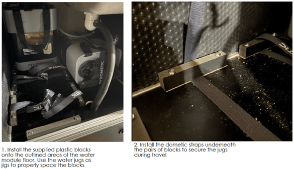
- Water Tank Installation
- Lower Water Module
- Water Module Assembly
Getting Started
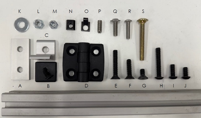
Module Assembly Hardware
A. Flat bracket
B. 8020 end cap
C. L bracket
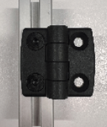
D. Hinge
E. 1.5" flatbed bolt
F. 1" flathead bolt
G. 0.5" flathead bolt
H. 1.5" button head bolt
I. 5/8" button head bolt
J. 0.5" button head bolt
K. 1/4" washer
L. 1/4-20 nylock nut
M. 10 mm nylock nut
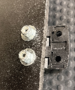
N. T-nut insert
O. Single tab clip
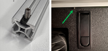
P. 1/4" stud
Q. M6 flange bolt
R. M5 button head bolt
S. M6 carriage bolt
T. 80/20 extrusion
Module Mounting Hardware
U. Square nut
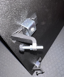
V. Mounting Bracket
W. M6 bolt
X. M6 Washer
Y. M6 lock washer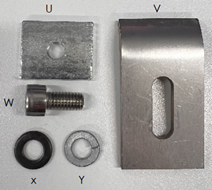
Required Tools
-
- 3mm, 4mm, 5mm hex key
- 7/16 Wrench
- Loctite (Blue)
Assembly Notes
-
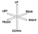
- All module renderings in module build instructions are oriented the same. See reference:
- Apply blue Locktite to all fasteners before install!
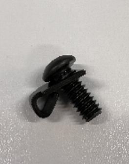
- Single Tab Clip (O) Orientation
- Install single tab clip onto 5/8" button head bolt (I) so that tab always faces away from head of bolt and tab faces toward the end of the 80/20 framing
- All module renderings in module build instructions are oriented the same. See reference:
- T-Nut Insert (N) Orientation
-
-
- Ensure T-Nut can slide freely in track of 80/20 framing
-
-
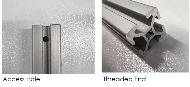
- 80/20 Frame Attachment Points
- Where 80/20 lengths connect to each other, each piece of framing will have a combination of access holes and threaded ends to facilitate assembly
- 80/20 Frame Attachment Points
-
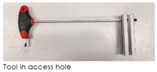
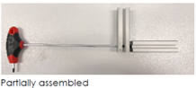
- Assembly Tool Instructions
- Use hex tools to screw bolts through access hole into threaded ends
- Assembly Tool Instructions
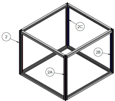
Frame Assembly
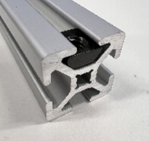
1. Slide in a 5/8 bolt (I) with a tab clip(O) into 80/20 frame track with clip inside track and tab facing end of frame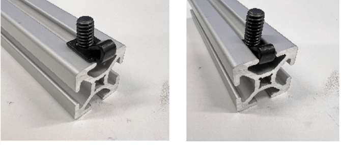
Incorrect Orientation Correct Orientation
2. Insert the tool through the access hole to meet bolt with tab clip
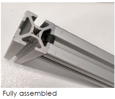
3. Screw the bolt into the threaded end of the receiving 80/20 length
4. Ensure that all connected edges are flush!
Mounting Module(s) to Camper
-
-
- When mounting multiple modules, it’s easiest to install seating modules prior to installing water and/or fridge module
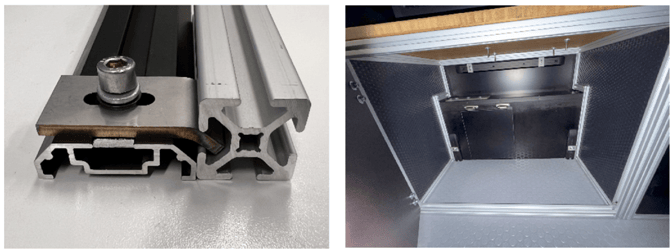
- Each module is mounted to camper using track lengths installed to camper floor pack
- There are 3 tracks: 1x horizontal track with 2 square nuts (U) pre-installed and 2x vertical tracks with 1square nut pre-installed.
- To attach a lower module:
- Align module into assigned location in camper
- Open cabinet door
- For each track, attach mounting bracket (V) using an M6 bolt (W) and M6 locking washer. Ensure that mounting bracket is oriented so that curve fits inside 80/20 frame and locks into place
-
Module Cabinet Door Assembly
-
-
- Cabinet door panel will be a 3/8 inch thick HDPE with pre drilled holes
- Attach 2x door hinges onto door panel using 1” flathead blots with 10mm nylock nut and ¼ washer
-
-
-
- Install hinges with door panel onto 80/20 frame using previously installed T-Nut insert (N) with .05 flathead bolt (G)
- Next, install provided latches onto door using M5 button head bolt (R)
- Once door is installed, adjust the strike pad for proper latch engagement with 80/20 frame
-
-
-
- Add 2x doorstops to 80/20 frame by installing ¼ studs (P) into previously installed T-Nuts (N). Ensure that doorstop is within 1/4” of the edge of the latches.
-
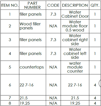
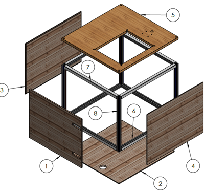
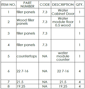
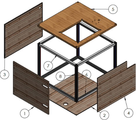
Water Module Assembly
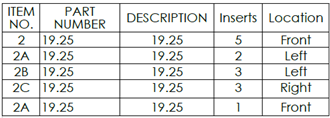
Lower Water Module Parts & Assembly
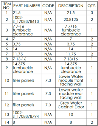
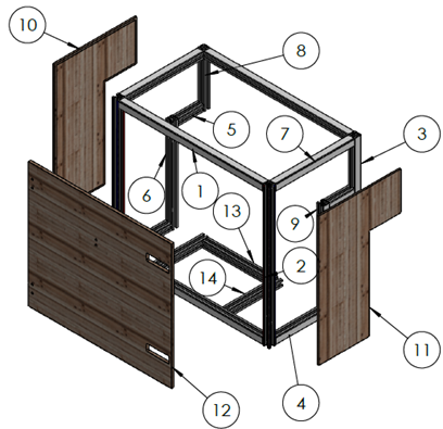
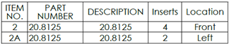
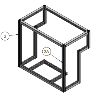
Lower Water Module Insert Parts & Location
Upper Water Module Parts & Assembly
5’ Upper Water Module Assembly
COM5 or COF5
Upper Water Module T- Nut Insert Locations
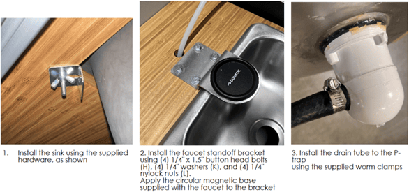
Sink, Faucet & Drain Assembly
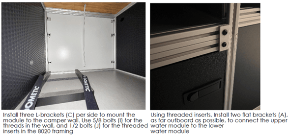
Connecting Lower & Upper Water Module
Water Tank Installation